
Getting Started Raspberry Pi Pico – Pinout, Specs – Beginner Guide
Table of Contents
Introduction
In this tutorial, we introduce the Raspberry Pi Pico hardware and software and show how to get started with the Raspberry Pi Pico and its features & specifications. We will also tell some basic features & Specifications and Pinout Details of Pico microcontrollers like ADC pins, I2C Pins, SPI Pins, and UART used to interface any sensors or modules.
You will learn how to set up the Raspberry Pi Pico and connect it to the computer. You will also learn to write simple programs to control the Raspberry Pi Pico.
What is Raspberry Pi Pico?
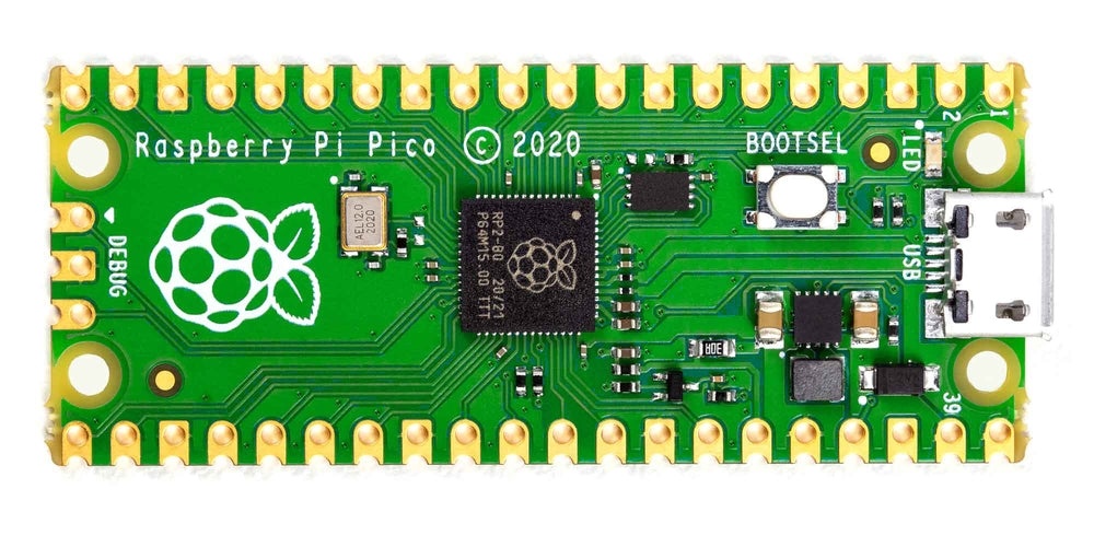
Raspberry Pi Pico is a low-cost, high-performance microcontroller with flexible digital interfaces. the board was made by Raspberry Pi Foundation in the UK. It was released in January 2021. It is designed for use in a wide range of applications, The board is based on the RP2040 microcontroller chip from Raspberry Pi, which we can program operating C/C++ and MicroPython. The RP2040 chip includes a dual-core cortex M0+ microcontroller that operates up to 133MHz. This chip offers 26 multi-function GPIO pins and 2MB of onboard Flash memory.
What is the RP2040 Microcontroller?

The RP2040 is the first microcontroller developed by the Raspberry Pi foundation. The RP2040 is a 32-bit dual ARM Cortex-M0+ microcontroller. The RP2040 microcontroller is low cost, with the Raspberry Pi Pico at US$4 and the RP2040 itself costing US$1. The microcontroller can be programmed in C/C++ and MicroPython
Behind the name 2040
The number 2 is for two cores because the RP2040’s CPU is a dual-core processor. The number 0 is for the CPU, an Arm Cortex M0+, and the number 4 is for 256KB of RAM 2 ^ 4 x 16KB. The final digit has no non-volatile storage on board.

The fix numeral on RP2040 comes from the following:
- RP in RP2040 means ‘Raspberry Pi’.
- Number of processor cores (2)
- Loosely which type of processor (M0+)
- The amount of RAM, from the function floor(log2(RAM / 16kB)); in this case it’s 256kB
- 0 means there is no non-volatile storage on board.
RP2040 features & Specifications:
| Processor | Dual ARM Cortex-M0+ cores |
| SPI Flash | 2M on-board QSPI |
| Maximum Clock Frequency (MHz) | 133 |
| SRAM | 264 |
| GPIO | 30 |
| PWM | 16 channels |
| ADC | 3 available × 12-bit |
| UART | 2 |
| I2C | 2 Buses |
| SPI | 2 Buses |
| Length (mm) | 25 |
| Width (mm) | 25 |
| Height (mm) | 8 |
| Weight (gm) | 8 |
| Shipment Weight | 0.01 kg |
| Shipment Dimensions | 6 × 3 × 1 cm |
Datasheet of RP2040 Download the datasheet of the RP2040 Microcontroller, click here.
Raspberry Pi Pico Specs & features :

Below, you can see the full specifications of the Raspberry Pi Pico
-

- CPU: 32-bit dual-core ARM Cortex-M0+ at 48MHz, configurable up to 133MHz
- RAM: 264kB of SRAM in six independently configurable banks
- Storage: 2MB external flash RAM
- GPIO: 26 pins
- ADC: 3 × 12-bit ADC pins
- PWM: Eight slices, two outputs per slice for 16 total
- Clock: Accurate on-chip clock and timer with year, month, day, day-of-week, hour, second, and automatic leap-year calculation
- Sensors: On-chip temperature sensor connected to 12-bit ADC channel)
- LEDs: On-board user-addressable LED
- Bus Connectivity: 2 × UART, 2 × SPI, 2 × I2C, Programmable Input/Output (PIO)
- Hardware Debug: Single-Wire Debug (SWD)
- Mount Options: Through-hole and castellated pins (unpopulated) with 4 × mounting holes
- Power: 5 V via a micro USB connector, 3.3 V via 3V3 pin, or 2–5V via VSYS pin

Among other deficiencies, the Raspberry Pi Pico does not have a digital-to-analogue converter (DAC, D/A, D2A, or D-to-A). It also does not have any kind of connectivity, be it Ethernet, WiFi, or Bluetooth, which makes it fail almost all the points for the IoT.
Raspberry Pi Pico Pinout
The next image is the pinout diagram of the Raspberry Pi Pico Board, it is 40 pins, which include Power, ground, UART, GPIO, PWM, ADC, SPI, I2C, system control, and Debugging pins. There’s a handy interactive pinout for Raspberry Pi Pico at pico.pinout.XYZ.

- VBUS: Connected directly to USB
- power (can be used to power Pico);
- VSYS: Connected via a diode to the USB power supply (can be used to power Pico without imposing voltage on the USB port);
- 3V3_EN: Connected to the “enable” pin of the switching chip (disables Pico when set to low level);
- 3v3(OUT): DC-DC converter output;
- ADC_VREF and AGND: Reference pins for the ADC (used when converter accuracy is a critical factor);
- ADC0-2: Analog-to-digital converters;
- I2c0-1: I2C ports (for each port, different pins can be used for the interface);
- RUN: Enables the RP2040 (when set to low level, it resets the system);
- SPIo-1: SPI ports (for each port, different pins can be used for the interface);
- UART0-1: UART ports (for each port, different pins can be used for the interface
Raspberry Pi Pico Pin Configurations
Below are the particular GPIO pin configuration details, the board features two rows of 20 GPIO pins, as well as a USB port, an SPI bus, and an I2C bus. The board can be powered by either a USB cable or a 3.3V power supply.

Raspberry Pi Pico – I2C Pins
The i2c has two lines: SDA (serial data) and SCL (serial clock). The i2c is used to send data between devices. The i2c can be used to connect devices to each other or to connect a device to a computer.
To set up an I2C, you specify the SCL and SDA pins being used. You can look for “SCL” and “SDA” in the pin names in the pinout diagram above.
- I2Cx_SCL = SCL
- I2Cx_SDA = SDA
| I2C Controller | GPIO Pins |
|---|---|
| I2C0 SDA | GP0/GP4/GP8/GP12/GP16/GP20 |
| I2C0 SCL | GP1/GP5/GP9/GP13/GP17/GP21 |
| I2C1 SDA | GP2/GP6/GP10/GP14/GP18/GP26 |
| I2C1 SCL | GP3/GP7/GP11/GP15/GP19/GP27 |
This Table shows the I2C pins on Raspberry Pi Pico
Raspberry Pi Pico – SPI Pins
SPI is an interface used to transmit data between microcontrollers and small peripherals such as sensors. It uses four separate wires to communicate: two for data, one for a clock signal, and one for chip selection. SPI is faster than I2C and only uses two wires, but this is more difficult to set up.
Raspberry Pi Pico microcontroller supports two SPI peripherals to confirm communication. SPI module pins are available through the GPIO pins of Raspberry Pi Pico.
| SPI0_RX | GP0/GP4/GP16 |
| SPI0_TX | GP3/GP7/GP19 |
| SPI0_CLK | GP2/GP6/GP18 |
| SPI0_CSn | GP1/GP5/GP17 |
| SPI1_RX | GP8/GP12/ |
| SPI1_TX | GP11/GP15/ |
| SPI1_CLK | GP10/GP14/ |
| SPI1_CSn | GP9/GP13/ |
Raspberry Pi Pico – UART Pins
The UART pins are a type of interface that is used for serial communication. There are two UART pins, one for transmitting (TX) and one for receiving (RX). The UART pins are used to connect devices that use serial communication, such as bluet, scanners, and modems.
RP2040 contains two identical UART peripherals with separate 32×8 Tx and 32×12 Rx FIFOs.
Below is the table for GPIOs pins that supports UART communication.
| UART0-TX | GP0/GP12/GP16 |
| UART0-RX | GP1/GP13/GP17 |
| UART1-TX | GP4/GP8 |
| UART1-RX | GP5/GP9 |
Raspberry Pi Pico – ADC Pins
The ADC pins on a microcontroller are used to convert an analog voltage into a digital number, The Raspberry Pi Pico board supports four analog pins with 12-bit ADC (analog to digital converters). But one of these four pins(ADC 4) is not provided as a GPIO pin on the pico board. This one pin is internally connected to the internal temperature sensor, by reading the analog value of ADC4.
ADC pins can be used to measure things like temperature, light level, or voltage from a potentiometer.
| ADC0 | GP26 |
| ADC1 | GP27 |
| ADC2 | GP28 |
Raspberry Pi Pico – PWM Pins
PWM pins are digital pins that are used to produce a pulse-width-modulated output signal. A PWM pin can be used to control the width of the Pulse Width Modulation (PWM) output signal, The Raspberry Pi Pico has 8-PWM block/slices(1-8)s and each PWM block provides two PWM signals through UART0 and UART1. That means each slice can drive up to two PWM signals.
The following factors influence the behaviour of a pulse width modulated signal:
- Frequency
- Duty Cycle
- Resolution
Raspberry Pi Pico Programming
The Raspberry Pi Pico is a microcontroller that can be programmed in a variety of languages, including C/C++ SDK and Micropython, They also provide their own SDKs for both C and Micropyhton.
After following the steps in this guide, you will have a Raspberry Pi Pico board up and running. You will have learned how to connect to the board and how to blink an LED using MicroPython code.
Sources
Raspberry Pi Pico
documentation
- Getting Started (PDF, general introduction, intended for beginners)
- Getting Started with MicroPython (PDF)
- Getting Started with C/C++ (PDF)
- Datasheet, Power Consumption (PDF)
- Other technical documentation
alternative systems
- Arduino Nano RP2040 Connect
- Adafruit Feather RP2040
- Adafruit Itsybitsy RP2040
- Spark Fun Thing Plus
- SparkFun Pro Micro
Read Similar Articles:
- Getting Started Raspberry Pi Pico – Pinout, Specs – Beginner Guide
- Interfacing PIR Motion Sensor with Raspberry Pi Pico
- Raspberry Pi Pico Home Automation System
- Interface Servo Motor With Raspberry Pi Pico
- Interface 0.96″ OLED Display with Raspberry Pi Pico
- Raspberry Pi Pico Weather Station Using Dht11 Sensor
- Interface 16*2 LCD Display With Raspberry Pi Pico


17 Comments