
Raspberry Pi Pico ADC | Tutorial
Table of Contents
This document describes the ADC functions available on the Raspberry Pi Pico ADC. The board features a 12-bit Analog-to-Digital Converter (ADC) and an onboard reference voltage. The ADC board is designed to work with the Raspberry Pi Pico computer, and it can be used to measure the voltage of an analogue signal. The board can be used to measure the voltage of a signal from 0 to 3.3 volts.
The Raspberry Pi Pico is built using an RP2040 microcontroller. The board exposes 26 multi-function GPIO pins from a total of 36 GPIO pins. Out of 36 GPIO Pins, There are 5 ADC pins but only 3 are usable. The ADC in Raspberry Pi Pico is **12-bit**, which is 4 times greater than the 10-bit ADC of the Arduino.
We’ll write a MicroPython code to learn how we can use the ADC pin value with any analog sensors. A potentiometer is the best tool to vary the input analog voltage. But before jumping directly into the ADC guide, it’s recommended to go through Raspberry Pi Pico Getting Started Tutorial.
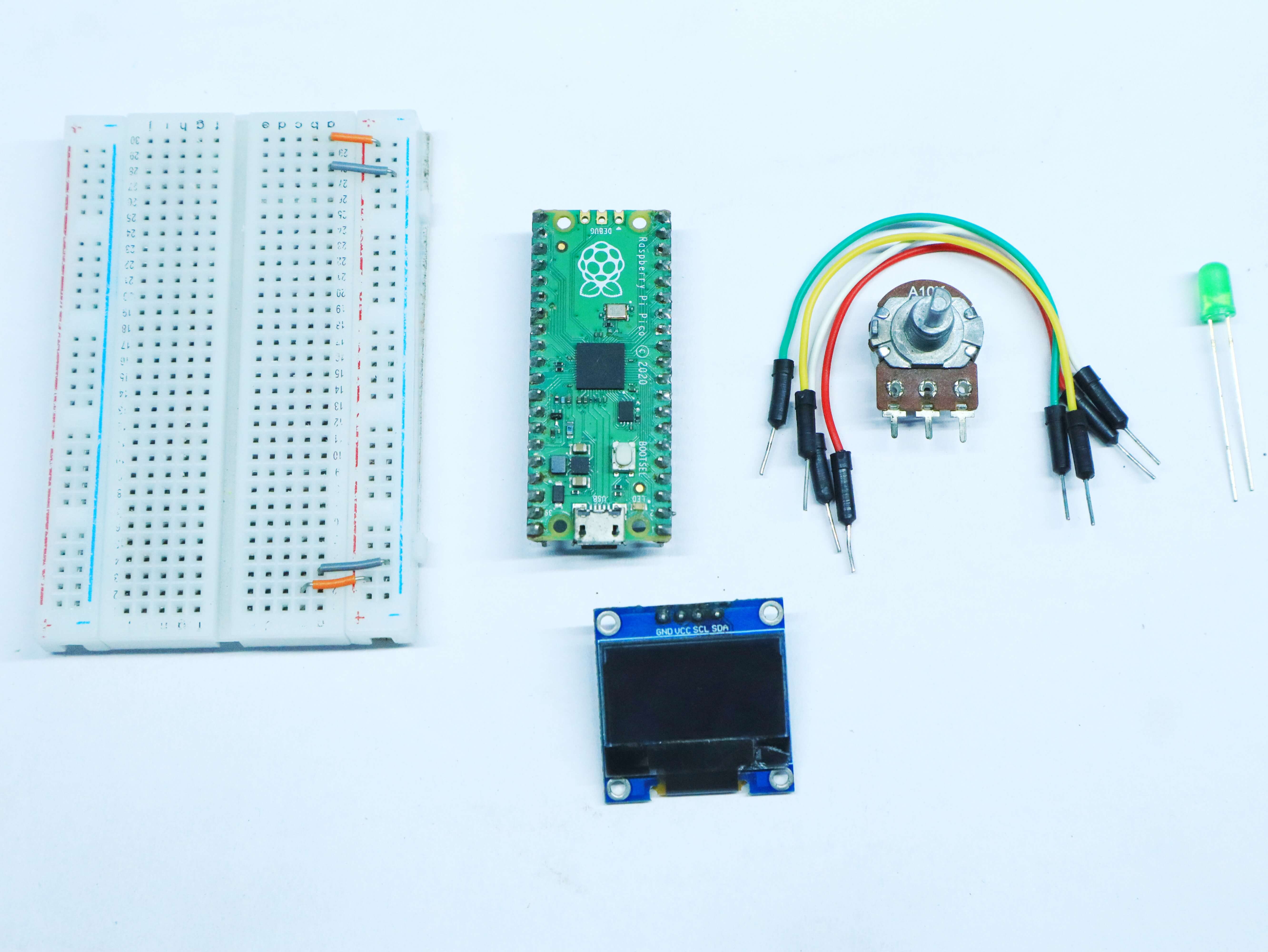
Required components:
- Raspberry Pi Pico
- 10k Potentiometer
- Connecting wires
What is Raspberry pi pico?
Raspberry Pi Pico is a tiny, fast, and versatile board based on RP2040, the company’s first microcontroller. The board has a USB port for power and data, and can be used with any computer or laptop. The board is fully programmable with the MicroPython language, and has a wide range of applications.
What is Analog to Digital Converter (ADC)?
The Analog Digital Converter (ADC) is a device that converts an analog signal, such as a sine wave, into a digital signal. The digital signal can then be processed by a digital signal processor (DSP) or microcontroller. An ADC typically has a resolution of 8, 10, 12, or 16 bits.
This means that it can represent 2^8, 2^10, 2^12, or 2^16 different levels of analog input signal. The number of bits also determines the maximum possible signal-to-noise ratio (SNR). The higher the SNR, the better the ADC can resolve small changes in the analog signal.
The main advantage of an ADC is that it can convert an analog signal into a digital signal that can be processed by a digital signal processor. This allows for more flexibility in the design of digital systems. For example, an ADC can be used to convert an audio signal into a digital signal that can be stored on a computer
How does an ADC work in a Microcontroller?
Most microcontrollers nowadays have built-in ADC converters. It is also possible to connect an external ADC converter to any type of microcontroller. The ADC in your Pico has 12-bit resolution, which means it can convert an analog signal into a digital signal as a number ranging from 0 to 4095, although this is handled in MicroPython transforming to a 16-bit number ranging from 0 to 65,535, to behave the same as the ADC in other MicroPython microcontrollers.
ADC in Raspberry Pi Pico board
As you can see from the below pinout diagram there are
- 30 multi-function General Purpose IO (4 can be used for ADC)(1.8-3.3V IO fixed Voltage)
- 2 × UART, 2 × I2C, 2 × SPI, 16 × PWM channels

The Raspberry Pi Pico is the first Raspberry Pi that has analog inputs from the manufacturer. It comes with a total of 5 ADC inputs (Analog Digital Converter). Two of these are connected to an internal temperature sensor integrated into the RP2040 and the second one can be used to measure the VSYS voltage monitoring on the board.
So how can having an analog input benefit you? Well, for example, one of my projects used a potentiometer to control LED. So, the Raspberry Pi Pico would be able to read the value of the potentiometer and use its values in the program that I have loaded onto it.
The Raspberry Pi Pico resolves ADC signals at 12-bits, which is better than the 10-bit ADC on the Arduino Uno. Other traits include:
- SAR ADC (successive approximation ADC)
- 500 kS/s (with external 48MHz clock)
- DMA interface on ADC inputs which can access memory without using the CPU
The next table shows you that the input signal for ADC0, ADC1 and ADC2 can be connected with GP26, GP27 & GP28 pins respectively.
| ADC Module | GPIO Pins |
| ADC0 | GP26 |
| ADC1 | GP27 |
| ADC2 | GP28 |
Read Analog values using Raspberry Pi Pico
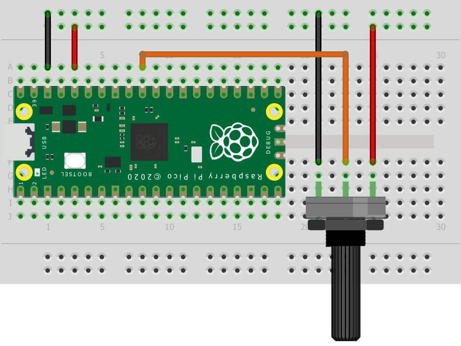
Connect pins 1 and 3 of the potentiometer to the 3.3V pin and GND pin of the Raspberry Pi Pico. Connect Pin 2 of the Potentiometer to the GP26 of the Raspberry Pi Pico.
 Let’s write a program to read varying analog values generated using a potentiometer which is connected to the A0 analogue channel. Display the analog value on the Serial monitor which we got from the Raspberry pi Pico ADC.
Raspberry pi pico analog Reading code
Now it’s time to write a code and check the Analog Reading. To do that you can use Thonny IDE. Copy the following code and hit the ‘Download & Run Button‘. Getting Started With Raspberry Pi Pico With Thonny IDE
|
1 2 3 4 5 6 7 8 9 |
import machine import utime analog_value = machine.ADC(26) while True: reading = analog_value.read_u16() print("ADC: ",reading) utime.sleep(0.2) |
Conclusion


Raspberry Pi Pico Pico ADC Measuring voltage
Now let’s understand how to use the Raspberry Pi Pico ADC. We will use the 10K potentiometer to change the analog input voltage. Let’s map analog voltage from 0 to 3.3V with 12-bit or 16-bit ADC. The connection diagram is delivered below.
For this example, we will connect a potentiometer to the microcontroller’s ADC pin and display in Thonny’s Shell the voltage reading that will vary between 0-3.3v
We will use the machine.ADC() function with the pin inside the function.
In this case, we read the value directly with potentiometer.read_u16(), multiply it by a conversion factor and print the value to the screen
Code – ADC Measuring voltage
Now it’s time to write a code and check the Analog Reading. To do that you can use Thonny IDE. Copy the following code and hit the ‘Download & Run Button‘.
|
1 2 3 4 5 6 7 8 9 10 11 |
import machine import utime potentiometer = machine.ADC(26) conversion_factor = 3.3 / (65535) while True: voltage = potentiometer.read_u16() * conversion_factor print(voltage) utime.sleep(0.1) |

Raspberry Pi Pico ADC – Measuring voltage Using OLED Display

How To Use SSD1306 Oled Display With Raspberry Pi Pico
Code – Measuring voltage Using OLED Display
|
1 2 3 4 5 6 7 8 9 10 11 12 13 14 15 16 17 18 19 20 21 22 23 24 25 26 27 28 29 30 31 32 33 34 35 36 37 38 39 40 41 42 43 |
from machine import Pin, I2C, ADC from ssd1306 import SSD1306_I2C # MicroPython SSD1306 OLED driver, I2C and SPI interfaces import utime analog_value = machine.ADC(26) conversion_factor = 3.3 / (65535) WIDTH = 128 # oled display width HEIGHT = 64 # oled display height i2c = I2C(0, scl=Pin(17), sda=Pin(16), freq=200000) # Init I2C using pins GP8 & GP9 (default I2C0 pins) oled = SSD1306_I2C(WIDTH, HEIGHT, i2c) # Init oled display # Clear the oled display in case it has junk on it. oled.fill(0) # Add some text oled.text("DIY",5,8) oled.text("Projects Lab",25,18) oled.text("ADC",25,40) oled.text("Tutorial",40,50) oled.show() utime.sleep(1) while True: oled.fill(0) reading = analog_value.read_u16() print("ADC: ",reading) utime.sleep(0.2) voltageValue = reading* conversion_factor oled.text("VOLTAGE",5,10) oled.text(str(voltageValue)+"V",20,40) oled.show() utime.sleep(1) |
Conclusion
Raspberry Pi Pico ADC + Potentiometer LED Dimmer
we will be looking at how to use the Raspberry Pi Pico ADC with a potentiometer to control the brightness of an LED. We will also be using the Raspberry Pi Pico GPIO pins to control the LED.
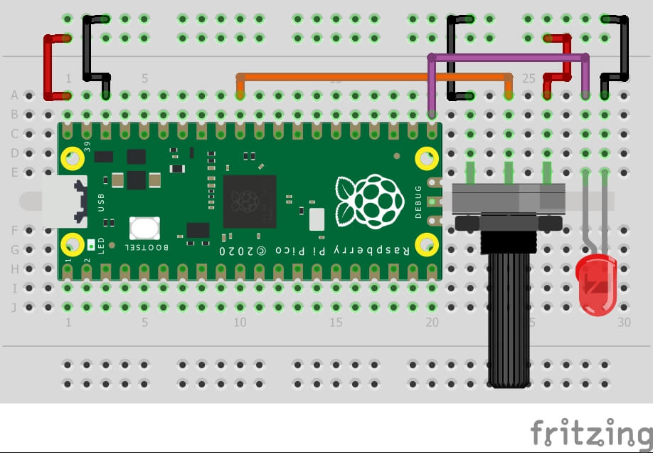
Code – Raspberry Pi Pico Potentiometer LED Dimmer
|
1 2 3 4 5 6 7 8 9 10 |
import machine import utime led_red = machine.PWM(machine.Pin(16)) potentiometer = machine.ADC(26) led_red.freq(1000) while True: led_red.duty_u16(potentiometer.read_u16()) |
Conclusion
Similar Raspberry Pi Pico Projects
- How To Use SSD1306 Oled Display With Raspberry Pi Pico
- RGB LED Using a Raspberry Pi Pico with MicroPython
- Joystick With Raspberry Pi Pico MicroPython Tutorial
- Flame Sensor With Raspberry Pi Pico Tutorial
- HC-SR04 Ultrasonic Distance Sensor With Raspberry Pi Pico Tutorial
- Raspberry Pi Pico Home Automation System
- Interface 16×2 Lcd Display With Raspberry Pi Pico
- Raspberry Pi Pico Weather Station Using Dht11 Sensor
- Interface Servo Motor With Raspberry Pi Pico
- Interfacing PIR Motion Sensor with Raspberry Pi Pico


