

Interface Rotary Encoder With Arduino, How It Works, Codes
Table of Contents
This reader explains how to use a rotary encoder with Arduino. It includes information on how the rotary encoder works, the code needed to use it, and the schematic for wiring it up. You can watch the following video or read the written tutorial below.
Overview
A rotary encoder is an input device that detects the amount of rotation of a shaft or dome. It is commonly used in robotics and machine control. The encoder can be connected to a microcontroller using an I2C or SPI interface, allowing it to be used to control motors and other devices.
There are two types of rotary encoders
- Absolute: Absolute encoders have a unique code for each position of the shaft, so they can keep track of the absolute position
- Incremental: Incremental encoders only keep track of changes in position, not the absolute position.
The absolute encoder provides us with the actual position of the knob in degrees while the incremental encoder declares how many increments the shaft has moved.
The rotary encoder used in this tutorial is of an incremental class.
Rotary encoder Vs Potentiometer Which one is better
Rotary encoders and potentiometers are two common ways to measure position or angle. So, which one is better?
There are pros and cons to each method. Rotary encoders are typically more accurate than potentiometers, but they can be more expensive. Potentiometers are less expensive, but they are not as accurate. Here are some things to consider when deciding between rotary encoders and potentiometers:
- Accuracy: If you need high accuracy, go with a rotary encoder. If you don’t need high accuracy, a potentiometer will suffice.
- Cost: Rotary encoders are more expensive than potentiometers.
- Easy of use: Rotary encoders can be more difficult to use than potentiometers.
- Environment: If your application will be in a difficult environment, go with a rotary encoder. Potentiometers can be more susceptible to dust and dirt.
In the end, it’s up to you to decide which method is best for your application. Consider the factors above and make the best decision for your needs. How Rotary Encoders Work
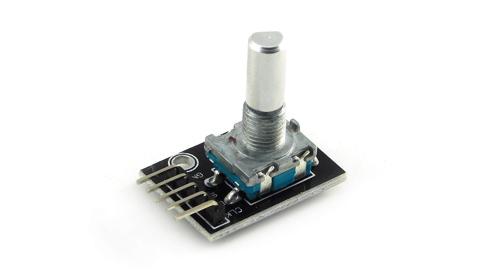
Rotary Encoder Pinout
The pinouts of the rotary encoder are as follows:

Description:
| Pin Name | Description |
| GND | Connected to GROUND |
| + | Connected to +5V |
| SW | The output of the internal button of the rotary encoder when pressed |
| DT | Contact A output or DATA |
| CLK | Contact B output or CLOCK |
Note: One of the DT or CLK pins must be connected to the interrupt of Arduino Uno, or both of the DT and CLK are attached to the interrupt pin.
Rotary Encoder Features and Specifications
- 360º free rotation.
- 20 steps or cycles per revolution
- Incremental type encoder
- Work on low voltages
- Maximum operating temperature: 0°C to + 80°C
- Easy interface
- Long life.
Applications
- Security systems.
- Motors
- CNC
- 3D Printer
- Robotic arms
- Vending machines.
- Industrial machines.
- Engineering systems.
- Measuring instruments.
- Hobby projects.
Wiring Diagram Rotary Encoder With Arduino

Source Code
Code for Reading Rotary Encoder With Arduino
|
1 2 3 4 5 6 7 8 9 10 11 12 13 14 15 16 17 18 19 20 21 22 23 24 25 26 27 28 29 30 31 32 33 34 35 36 37 38 39 40 41 42 43 44 45 46 47 48 49 50 51 52 53 54 55 56 57 58 59 60 61 62 63 64 65 66 67 68 69 70 71 72 |
// Rotary Encoder Inputs #define CLK 2 #define DT 3 #define SW 4 int counter = 0; int currentStateCLK; int lastStateCLK; String currentDir =""; unsigned long lastButtonPress = 0; void setup() { // Set encoder pins as inputs pinMode(CLK,INPUT); pinMode(DT,INPUT); pinMode(SW, INPUT_PULLUP); // Setup Serial Monitor Serial.begin(9600); // Read the initial state of CLK lastStateCLK = digitalRead(CLK); } void loop() { // Read the current state of CLK currentStateCLK = digitalRead(CLK); // If last and current state of CLK are different, then pulse occurred // React to only 1 state change to avoid double count if (currentStateCLK != lastStateCLK && currentStateCLK == 1){ // If the DT state is different than the CLK state then // the encoder is rotating CCW so decrement if (digitalRead(DT) != currentStateCLK) { counter --; currentDir ="CCW"; } else { // Encoder is rotating CW so increment counter ++; currentDir ="CW"; } Serial.print("Direction: "); Serial.print(currentDir); Serial.print(" | Counter: "); Serial.println(counter); } // Remember last CLK state lastStateCLK = currentStateCLK; // Read the button state int btnState = digitalRead(SW); //If we detect LOW signal, button is pressed if (btnState == LOW) { //if 50ms have passed since last LOW pulse, it means that the //button has been pressed, released and pressed again if (millis() - lastButtonPress > 50) { Serial.println("Button pressed!"); } // Remember last button press event lastButtonPress = millis(); } // Put in a slight delay to help debounce the reading delay(1); } |
Code for Understanding Rotary Encoder Position
Here’s a complete Arduino code where the encoder value is printed out of the serial port in IDE
|
1 2 3 4 5 6 7 8 9 10 11 12 13 14 15 16 17 18 19 20 21 22 23 24 25 26 27 28 29 30 |
int encoder_vaue = 0; int DT_pin = 6; int CLK_pin = 7; int DT_pinstate; int last_DT_pinstate; void setup() { pinMode (DT_pin, INPUT); pinMode (CLK_pin, ,INPUT); Serial.begin (9600); // Reads the initial state of DT last_DT_pinstate = digitalRead(DT_pin); } void loop() { if (DT_pinstate != last_DT_pinstate) { //did DT changed state? if (digitalRead(CLK_pin) == DT_pinstate) { // if DT changed state, check CLK encoder_value--; // rotation is clockwise, decrement the value }else{ encoder_value++; // rotation is counter-clockwise, increment the value } last_DT_pinstate = DT_pinstate; //save the last state of DT Serial.print("Position: "); Serial.println(encoder_value); } last_DT_pinstate = DT_pinstate; // Updates the previous state of DT with the current state } |
Using Interrupts
Rotary encoders can be used with interrupts to provide more accurate speed and position measurements. Interrupts are signals that tell the processor to stop what it is doing and attend to something else. Hardware interrupts are typically used for time-critical tasks like handling keyboard input or playing sound. Software interrupts are typically used for less time-critical tasks like updating the screen or checking for new data.
Rotary encoders can use either type of interrupt. Hardware interrupts are more accurate but take longer to process. Interrupts can be used to measure the time between pulses
Here’s the sketch that documents the use of the interrupts while reading a rotary encoder.
|
1 2 3 4 5 6 7 8 9 10 11 12 13 14 15 16 17 18 19 20 21 22 23 24 25 26 27 28 29 30 31 32 33 34 35 36 37 38 39 40 41 42 43 44 45 46 47 48 49 50 51 52 53 54 55 56 57 58 59 |
// Rotary Encoder Inputs #define CLK 2 #define DT 3 int counter = 0; int currentStateCLK; int lastStateCLK; String currentDir =""; void setup() { // Set encoder pins as inputs pinMode(CLK,INPUT); pinMode(DT,INPUT); // Setup Serial Monitor Serial.begin(9600); // Read the initial state of CLK lastStateCLK = digitalRead(CLK); // Call updateEncoder() when any high/low changed seen // on interrupt 0 (pin 2), or interrupt 1 (pin 3) attachInterrupt(0, updateEncoder, CHANGE); attachInterrupt(1, updateEncoder, CHANGE); } void loop() { //Do some useful stuff here } void updateEncoder(){ // Read the current state of CLK currentStateCLK = digitalRead(CLK); // If last and current state of CLK are different, then pulse occurred // React to only 1 state change to avoid double count if (currentStateCLK != lastStateCLK && currentStateCLK == 1){ // If the DT state is different than the CLK state then // the encoder is rotating CCW so decrement if (digitalRead(DT) != currentStateCLK) { counter --; currentDir ="CCW"; } else { // Encoder is rotating CW so increment counter ++; currentDir ="CW"; } Serial.print("Direction: "); Serial.print(currentDir); Serial.print(" | Counter: "); Serial.println(counter); } // Remember last CLK state lastStateCLK = currentStateCLK; } |
Did this writing help you understand rotary encoders? If it did, kindly leave a comment down!


One Comment